
Possible Backplane and Cabling Configurations
A practical overview of backplane, controller, and internal cabling options for the Dell PowerEdge R640 server. This article is based on the technical diagrams in the service manual and translates them into a more readable format for configuration selection, service, and storage upgrades.
Quick Summary of Variants
How to Read Diagrams in the Manual
Several key elements are repeated in Dell's service illustrations. The backplane is the disk mid-plane into which drives are inserted. For 10 × 2.5" variants, a backplane expander is also present, extending connectivity for more positions. Additionally, there are signal cables, power cables, SAS/SATA cables, and, depending on the configuration, NVMe cables. If a 2 × 2.5" rear backplane is installed, separate power and signal wiring for the rear backplane are added.
The difference between a Mini PERC and an adapter PERC lies in the controller's location and the cabling path. With a Mini PERC, cabling typically routes directly to the Mini PERC module or storage connector. With an adapter PERC, SAS connectivity is switched to the PERC11 card, which is clearly visible especially in the later diagrams of the chapter.
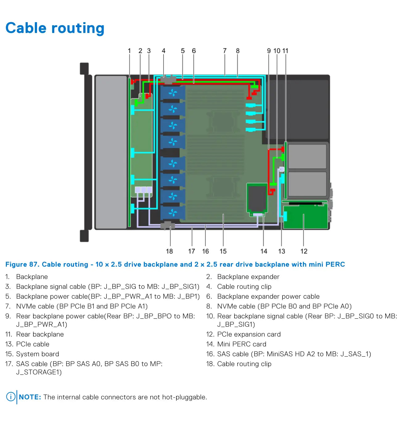
10 × 2.5" Front Backplane + 2 × 2.5" Rear Backplane with Mini PERC
This variant combines a full ten-position front backplane, a two-position rear backplane, and a Mini PERC controller. Compared to simpler configurations, this adds rear power and signal cables for the rear backplane.
The diagram also shows a pair of NVMe cable pairs, a PCIe cable for the expansion card, and two important SAS connections – one from the main backplane and the other to the rear backplane. This is therefore one of the most complex cabling configurations in the entire chapter.
- backplane + backplane expander in the front section
- rear backplane 2 × 2.5" with separate power and signal cable
- Mini PERC card
- PCIe expansion card and separate PCIe cable
- two NVMe pairs: BP PCIe B1/A1 and BP PCIe B0/A0
- SAS routing from backplane to storage connector
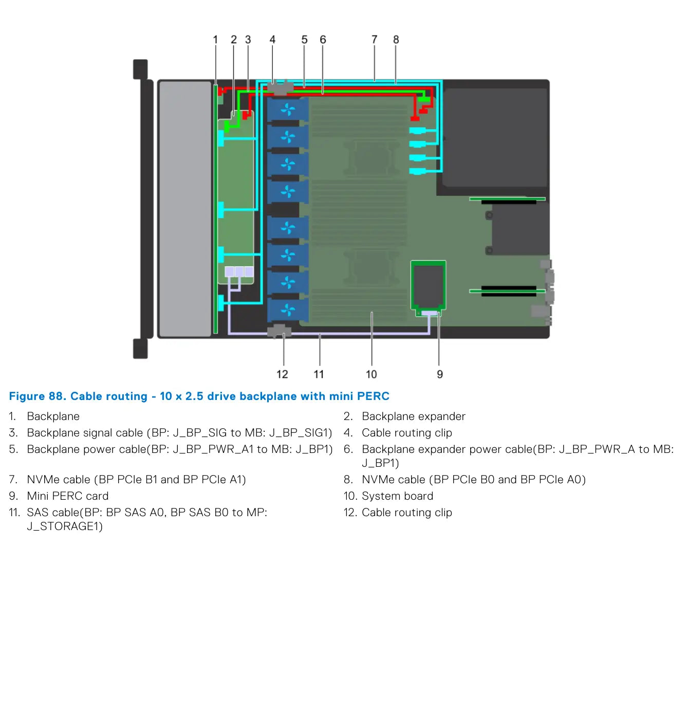
10 × 2.5" Backplane with Mini PERC
This configuration is simpler than the previous one, as it lacks the rear backplane and its cabling. However, it retains the backplane expander, two NVMe cable pairs, and SAS connection to the Mini PERC.
For servicing, this is a good reference model for the ten-position 2.5" platform, from which other NVMe and PERC11 variants are derived.
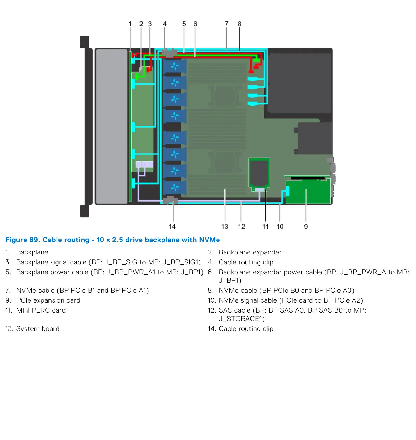
10 × 2.5" Backplane with NVMe
For the NVMe variant, a separately drawn NVMe signal cable from the PCIe expansion card to the BP PCIe A2 connector is added. This confirms that some communication no longer runs only through classic SAS cabling and controller, but directly through PCIe/NVMe interconnection.
The Mini PERC is still present in the image, as the configuration can combine the SAS/SATA part with the NVMe layer in the same chassis.
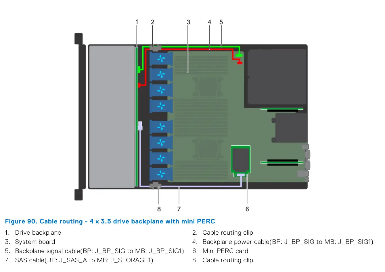
4 × 3.5" and 8 × 2.5" with Mini PERC or onboard SATA
Page 104 shows two basic combinations with Mini PERC: 4 × 3.5" and 8 × 2.5". In both cases, the diagram is significantly simpler than for the 10 × 2.5" platform, as there is no backplane expander.
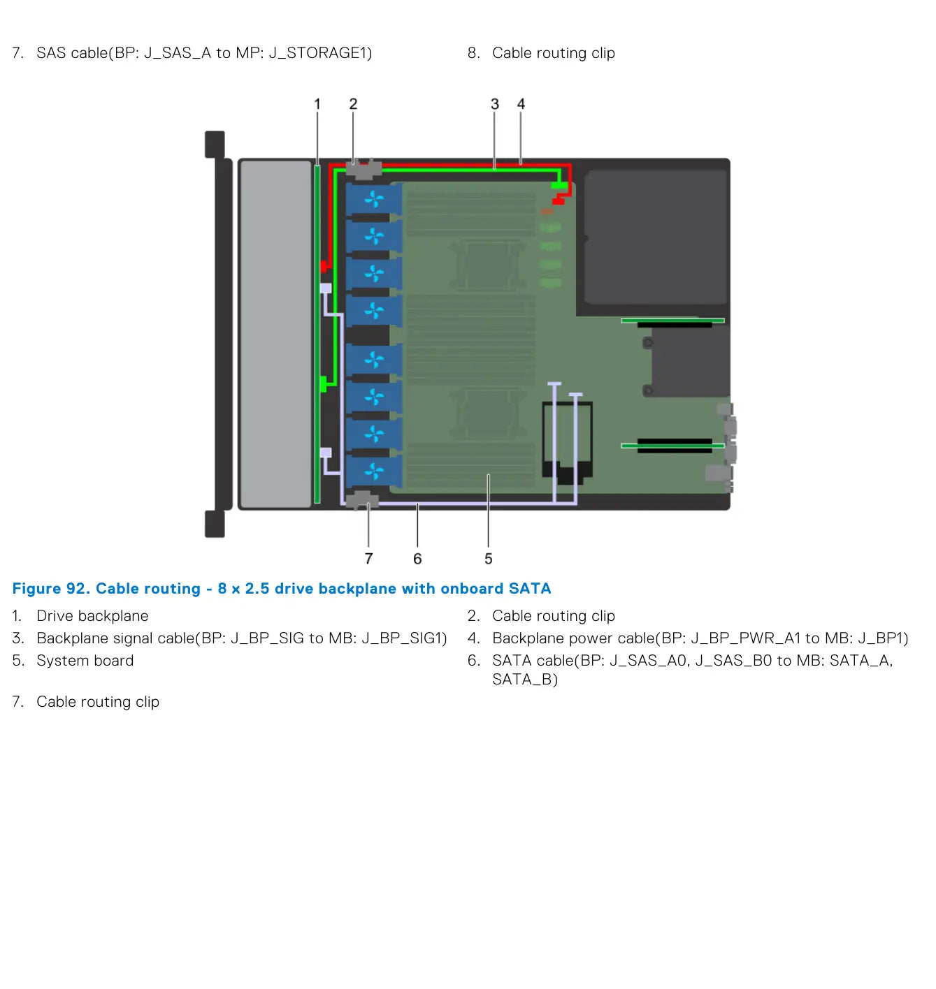
Page 105 also includes an 8 × 2.5" variant with onboard SATA. This clearly shows the difference between a hardware controller and direct SATA connection to the system board.
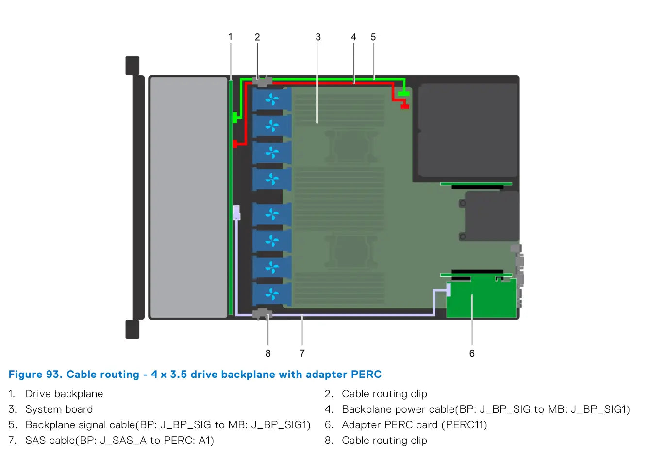
4 × 3.5" + rear 2 × 2.5" and 8 × 2.5" with adapter PERC
Page 106 features a 4 × 3.5" configuration with an adapter PERC, i.e., with a PERC11 card. It also introduces the 4 × 3.5" + 2 × 2.5" rear backplane with NVMe configuration, which continues on page 107.
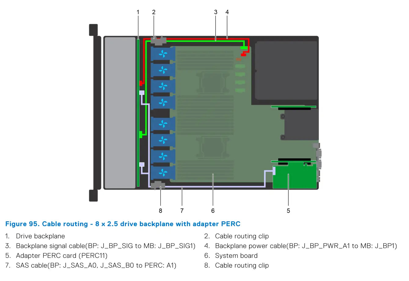
Page 107 then completes the rear backplane variant and adds an 8 × 2.5" configuration with an adapter PERC. Dell thus distinguishes cabling not only by disk type but also by the physical implementation of the controller.
10 × 2.5" with adapter PERC, rear backplane, 4 NVMe and 8 NVMe
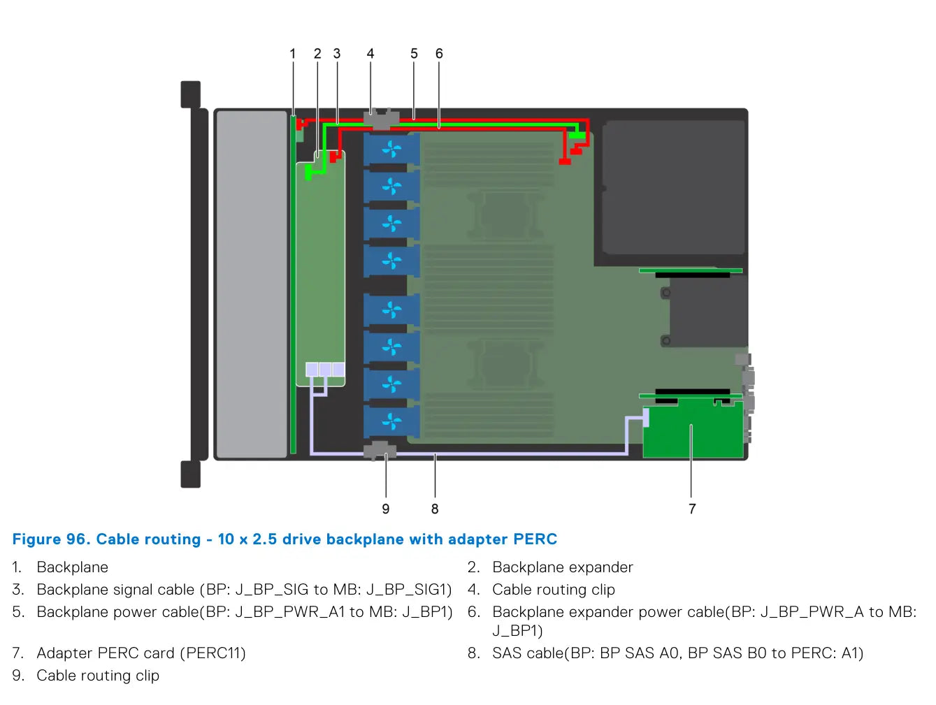
The last block is most important for high-end R640 configurations. Page 108 shows 10 × 2.5" with an adapter PERC. This is immediately followed by 10 × 2.5" + 2 × 2.5" rear backplane with onboard SATA, completed on page 109.
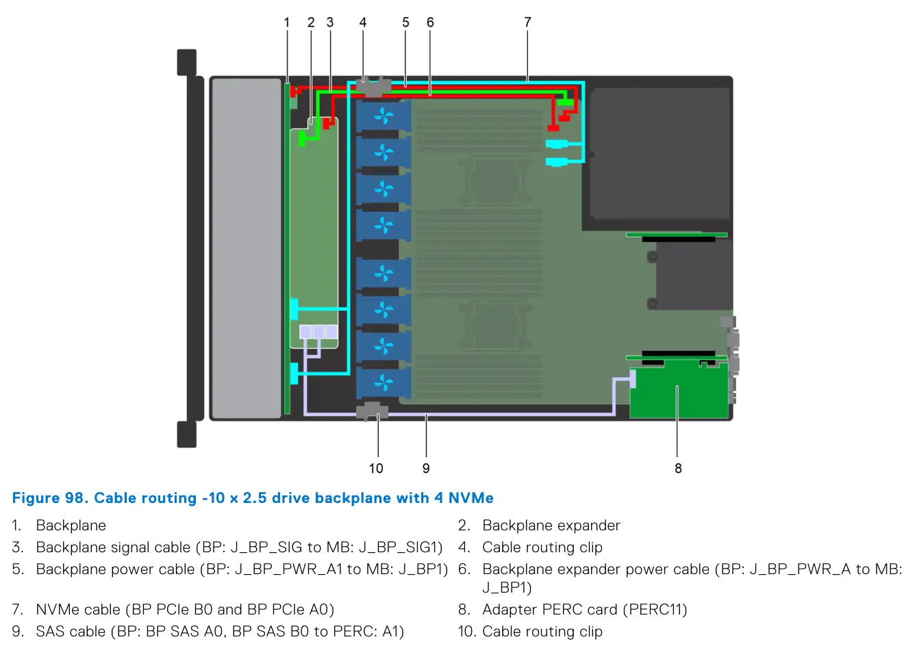
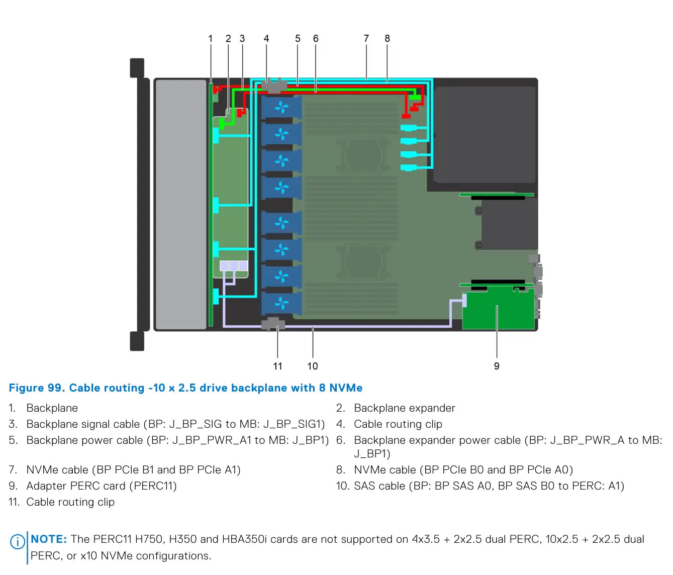
Pages 109–110 then show two pure NVMe variants: 10 × 2.5" with 4 NVMe and 10 × 2.5" with 8 NVMe. In both cases, the backplane expander, power and signal routing, and, if needed, an adapter PERC for the SAS portion of the system remain.
- 10 × 2.5" adapter PERC: SAS from BP SAS A0/B0 to PERC: A1
- 10 × 2.5" + rear 2 × 2.5" onboard SATA: rear power + rear signal + SAS to rear backplane
- 10 × 2.5" with 4 NVMe: only a pair of NVMe cables B0/A0 is shown
- 10 × 2.5" with 8 NVMe: both NVMe pairs B1/A1 and B0/A0 are shown
Key Notes for Compatibility and Service
- The 10 × 2.5" platform is the most complex in terms of cabling, as it can combine an expander, PERC, NVMe, and a rear backplane.
- The 8 × 2.5" is a very versatile configuration – it can run with a Mini PERC, adapter PERC, or purely via onboard SATA.
- The 4 × 3.5" is the simplest in terms of cable management, but even here there is a difference between Mini PERC and PERC11.
- If a 2 × 2.5" rear backplane is added, both power and signal wiring are always extended, and it is necessary to check the correct cable routing in the space behind the drives.
- The manual states compatibility limitations for some PERC11 configurations, especially in conjunction with dual PERC and 10 × NVMe variants.
Share:
Refurbished DELL servers - are they worth it?
Dell PowerEdge R440 vs Dell PowerEdge R450: Which is a better buy in April 2026